Tutorial: OEC-1 Miravalles Geothermal System Modelling
Introduction
This tutorial will introduce modelling a real geothermal power station as an Organic Rankine Cycle (ORC) in Excel using JSteam. Please ensure you have read the Getting Started Guide before starting this tutorial.
The ORC system that will be modeled is the OEC-1 Miravalles Unit 5 in the Guanacaste Province in Costa Rica. The model will be based on the Heat and Mass Balance (H&MB) data of the plant obtained from [1].
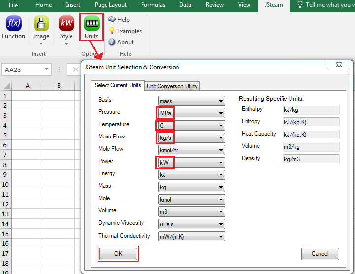
Note: This model uses the same units as the reference, which are not the default JSteam units. Before starting this tutorial, please change the units to (°C, MPa, kg/s, kW), as below.
Step 1 - Draw the PFD
We will commence by building the Process Flow Diagram (PFD) of the plant. Begin by starting a new workbook in Excel (with the above unit changes), and drawing the PFD exactly as you see in the finished example below:
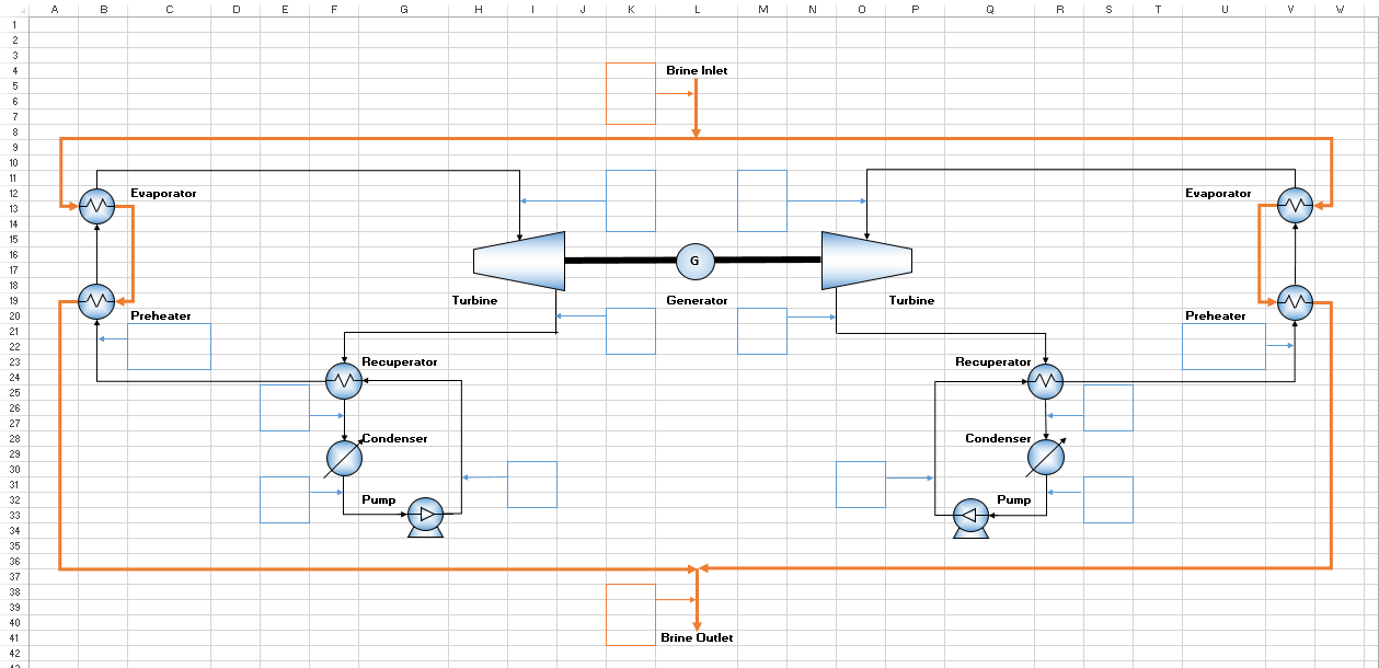
Please note that you may open the finished PFD from the Examples directory inside the JSteam installation directory if you wish to skip this step.
Step 2 - Add the Unit Operation Models
Rather than adding all the unit operation data to the PFD, we will use another Excel worksheet (but in the same workbook) to add the unit details. Rename Sheet1 to "ORC_Unit_Operations" by double clicking on the respective sheet tab, and move to the empty unit operations worksheet.
According to [1], the thermodynamic conditions of the ORC system on the left-hand side are identical to the right-hand side. Therefore, we will only need to analyze one side (i.e. the left-hand side) of the system and copy the results to the right-hand side (you are welcome to model both sides, but this is just an example). In addition, to simplify our analysis, we will combine the preheater and the evaporator together into one heater unit, which is thermodynamically equivalent. This means that in the ORC_Unit_Operations sheet, we will only need to include 1 Turbine function, 4 Heat Exchanger functions, and 1 Pump function.
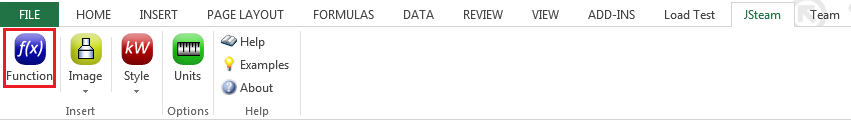
We will first insert the Turbine function, which for this model is a single-stage flow-based unit operation. In the unit operations worksheet, click on cell A1 and type "Turbine". If you like, you can merge and center it with cell B1, and make it bold so the title stands out better (optional). Now click on cell A2 and go to the Function button in the JSteam tab at top of the Excel window, as shown below:
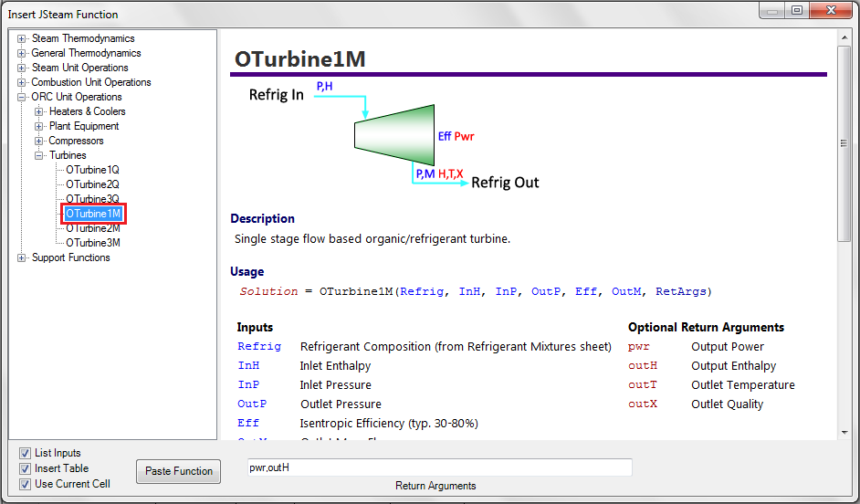
A new window called "Insert JSteam Function" will pop up. In the Insert JSteam Function window go to ORC Unit Operations -> Turbines -> OTurbine1M and then click on the Paste Function button, as shown below:
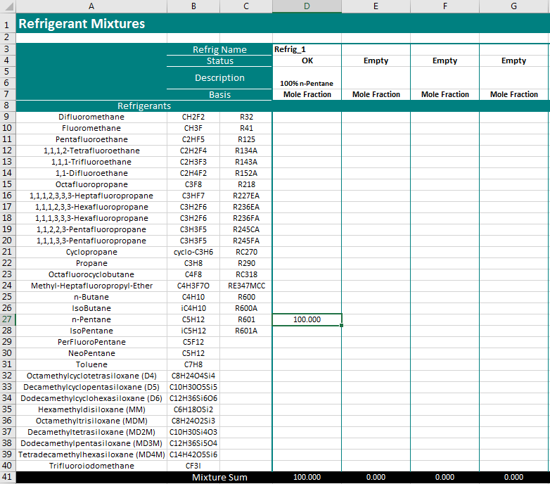
Notice that once you paste your function into your worksheet, another Excel worksheet called "RefrigMixtures" will automatically be added. This worksheet will be used to specify the working fluid of the ORC system. For this particular plant, the working fluid is n-Pentane. By default, JSteam will assume that the working fluid is pure n-Butane. To change the working fluid to n-Pentane, go to the RefrigMixtures sheet and type 100.00 in cell D27 and delete the number in cell D25. Your RefrigMixtures worksheet should look like the figure below:
We will now insert the remaining 2 Cooler functions, 2 Heater functions, and 1 Pump function that are associated with the left-hand side of the ORC system in the unit operations sheet:
Recuperator (Cooler) - Type "Recuperator (Cooler)" in cell D1. Click on cell D2 and then go to ORC Unit Operations -> Heaters & Coolers -> OCoolerTM and then click on the Paste Function button.
Condenser - Type "Condenser" in cell G1. Click on cell G2 and then go to ORC Unit Operations -> Heaters & Coolers -> OCoolerTM and then click on the Paste Function button.
Pump - Type "Pump" in cell J1. Click on cell J2 and then go to ORC Unit Operations -> Plant Equipment -> OPump and then click on the Paste Function button.
Recuperator (Heater) - Type "Recuperator (Heater)" in cell D11. Click on cell D12 and then go to ORC Unit Operations -> Heaters & Coolers -> OHeaterTM and then click on the Paste Function button.
Preheater + Evaporator - Type "Preheater + Evaporator" in cell G11. Click on cell G12 and then go to ORC Unit Operations -> Heaters & Coolers -> OHeaterTQ and then click on the Paste Function button.
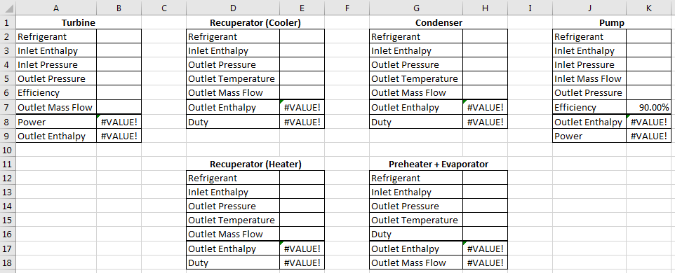
Once you have inserted all the JSteam functions above, your ORC_Unit_Operations sheet should look like the figure below:
Step 3 - Enter the H&MB Data
We can now start to fill in the temperature and pressure values within the PFD sheet. The majority of these values come directly from [1], however some will be calculated by our model. For each value, ensure you paste the correct style in each cell.
Turbine
- Inlet Pressure - Enter 1.53 in cell K11.
- Inlet Temperature - For the turbine inlet temperature, we will be calculating this value by assuming it is saturated vapour + a very small amount of superheating. This tiny value ensures the fluid temperature always results in a vapour, which is required when operating close to the saturation line. Type the following expression in cell K12:
=TsatmP(RefrigMixtures!D3,PFD!K11)+0.001 - Outlet Pressure - Enter 0.135 in cell K20.
Recuperator
- Inlet Pressure - Enter 1.64 in cell I30.
- Outlet Pressure - Enter 0.135 in cell E25.
- Outlet Temperature - Enter 65 in cell E26.
Condenser
- Outlet Pressure - Enter 0.125 in cell E31.
- Outlet Temperature - Enter 42.36 in cell E32.
Preheater
- Inlet Pressure - Enter 1.64 in cell C21.
- Inlet Temperature - Enter 61.1 in cell C22.
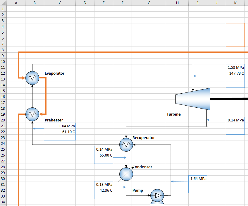
Your PFD should now look like the below figure, noting some of the pressure values have been rounded for display only:
Step 4 - Enter Brine Information
From the acceptance tests described in [1] we know that the mass flow of the brine is 398.4 kg/s, the inlet pressure is 0.835 MPa, the inlet temperature is 166.90 °C, and the outlet temperature is 136 °C. Therefore, enter the following within the PFD sheet:
Brine Inlet
- Pressure - Enter 0.835 in cell K4.
- Temperature - Enter 166.9 in cell K5.
- Mass Flow - Enter 398.4 in cell K7.
Brine Outlet
- Pressure - Enter 0.835 in cell K38.
- Temperature - Enter 136 in cell K39.
- Mass Flow - Enter 398.4 in cell K41.
As before, insert the respective Style (unit) to each cell.
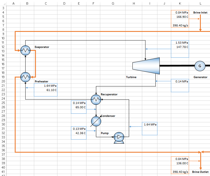
After you have completed entering all the pressure, temperature and mass flow values in both Step 3 and 4, your PFD should look like the figure below:
Do note that due to the limited information about the brine in [1], we have assumed that there is no pressure drop between the inlet and outlet brine. This can be easily added if this information is available.
Step 5 - Enter Turbine Specifications
Now we are ready to begin calculating the unknowns in the model using the JSteam functions we inserted previously, together with the pressure and temperature values in the PFD sheet. Return to the ORC_Unit_Operations sheet and enter the following expressions as shown below:
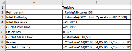
- Refrigerant - Reference to cell RefrigMixtures!D3, which we have specified to be n-Pentane.
- Inlet Enthalpy - We want to pass the outlet enthalpy of the Preheater + Evaporator function, i.e. cell H17, into this cell. However, we have not yet calculated the Preheater + Evaporator's outlet enthalpy hence we need to use the Estimate function to first estimate the inlet enthalpy until it is calculated. In this case, our guess is 500 kJ/kg.
- Inlet Pressure - Reference to cell PFD!K11 (Preheater + Evaporator Outlet Pressure)
- Outlet Pressure - Reference to cell PFD!K20 (Recuperator (Cooler) Inlet Pressure).
- Efficiency - The isentropic efficiency of this particular turbine is 82.71%.
- Outlet Mass Flow - Since the mass flow of n-Pentane will be obtained from cell H18, we have to also use the Estimate function to estimate the mass flow until it is calculated later. We will guess that the mass flow of n-Pentane is 50 kg/s.
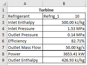
After you have entered the expressions above you should get the following results:
Step 6 - Enter Recuperator (Cooler) Specifications
For the Recuperator (Cooler) function, enter the following expressions as shown below:
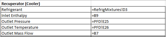
- Refrigerant - Reference to cell RefrigMixtures!D3.
- Inlet Enthalpy - Reference to cell B9 (Turbine Outlet Enthalpy).
- Outlet Pressure - Reference to cell PFD!E25 (Condenser Inlet Pressure).
- Outlet Temperature - Reference to cell PFD!E26 (Condenser Inlet Temperature).
- Outlet Mass Flow - Reference to cell B7.
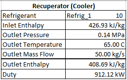
After entering the expressions above you should get the following outputs:
Step 7 - Enter Condenser Specifications
For the Condenser function, enter the following expressions as shown below:
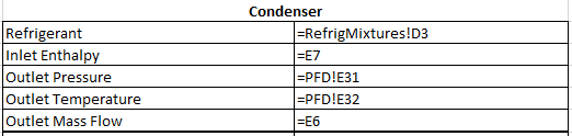
- Refrigerant - Reference to cell RefrigMixtures!D3.
- Inlet Enthalpy - Reference to cell E7 (Recuperator (Cooler) Outlet Enthalpy)
- Outlet Pressure - Reference to cell PFD!E31 (Pump Inlet Pressure).
- Outlet Temperature - Reference to cell PFD!E32 (Pump Inlet Temperature).
- Outlet Mass Flow - Reference to cell E6 (Recuperator (Cooler) Outlet Mass Flow).
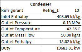
After entering the expressions above you should get the following outputs:
Step 8 - Enter Pump Specifications
For the Pump function, enter the following expressions as shown below:
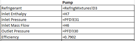
- Refrigerant - Reference to cell RefrigMixtures!D3.
- Inlet Enthalpy - Reference to cell H7 (Condenser Outlet Enthalpy)
- Inlet Pressure - Reference to cell PFD!E31 (Condenser Outlet Pressure).
- Outlet Mass Flow - Reference to cell H6 (Condenser Outlet Mass Flow).
- Outlet Pressure - Reference to cell PFD!I30 (Recuperator (Heater) Inlet Pressure).
- Efficiency - The isentropic efficiency of this particular pump is 79.02%.
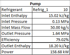
Once you have entered the expressed above you should get the following results:
Step 9 - Enter Recuperator (Heater) Specifications
For the Recuperator (Heater) Function, enter the following expressions as shown below:
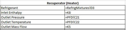
- Refrigerant - Reference to cell RefrigMixtures!D3.
- Inlet Enthalpy - Reference to cell K8 (Pump Outlet Enthalpy)
- Outlet Pressure - Reference to cell PFD!C21 (Preheater + Evaporator Inlet pressure).
- Outlet Temperature - Reference to cell PFD!C22 (Preheater + Evaporator Inlet Temperature).
- Outlet Mass Flow - Reference to cell K5 (Pump Inlet (+Outlet) Mass Flow).
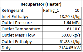
After entering the expressions above you should get the following outputs:
Step 10 - Enter Preheater + Evaporator Specifications
Before we find the outputs of the Preheater + Evaporator function, we need to first find the inlet and outlet enthalpy of the brine. We will assume that the brine is pure water, however future versions of JSteam will add brine-specific thermodynamics.
Go to the PFD sheet and enter the following expression:
- Inlet Enthalpy - Enter
=HPT(K4, K5)in cell K6. - Outlet Enthalpy - Enter
=HPT(K38, K39)in cell K40.
Now to find the outputs of the Preheater + Evaporator function, enter the following expressions as shown below:
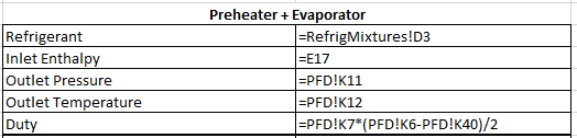
- Refrigerant - Reference to cell RefrigMixtures!D3, which we specified to be n-Pentane.
- Inlet Enthalpy - Reference to cell E17 (Recuperator (Heater) Outlet Enthalpy)
- Outlet Pressure - Reference to cell PFD!K11 (Turbine Inlet Pressure).
- Outlet Temperature - Reference to cell PFD!K12 (Turbine Inlet Temperature).
- Duty - If we assume that there is no heat loss across all the heat exchangers, then the duty of the Preheater + Evaporator is equal to the heat transferred from the brine. To calculate the duty, it is the mass flow rate of the brine multiplied by the inlet enthalpy minus the outlet enthalpy of the brine. Notice that we also divide the duty by two because we are only dealing with the left-hand side of the ORC system.
After entering the expressions above you should get the following results:
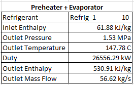
Note: The Excel iterative solver will now replace the estimates we made earlier with actual calculated values.
Step 11 - Importing the Enthalpy and the Mass Flow Rate Values to the PFD
Once you have completed Step 5 to Step 10, all of your JSteam functions would have been filled in and should look like the figure below:
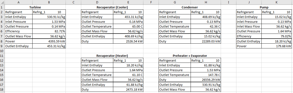
Note: the duty of the cold side of the recuperator is not equal to the duty of the hot side. This is because this example is using real plant data, where it is evident there is different heat transfer characteristics through each side of the heat exchanger. While this is typical with real data, if you are completing simple design exercises you may prefer to link the duty between both the heater and cooler via a heater or cooler with duty as an input.
We are now ready to copy the output enthalpy of each function and the mass flow rate to the PFD sheet. Go to the PFD sheet and enter the following expressions to the respective cells:
- K22 -
=ORC_Unit_Operations!B9 - E27 -
=ORC_Unit_Operations!E7 - E33 -
=ORC_Unit_Operations!H7 - I32 -
=ORC_Unit_Operations!K8 - C23 -
=ORC_Unit_Operations!E17 - K13 -
=ORC_Unit_Operations!H17 - K14 -
=ORC_Unit_Operations!H18
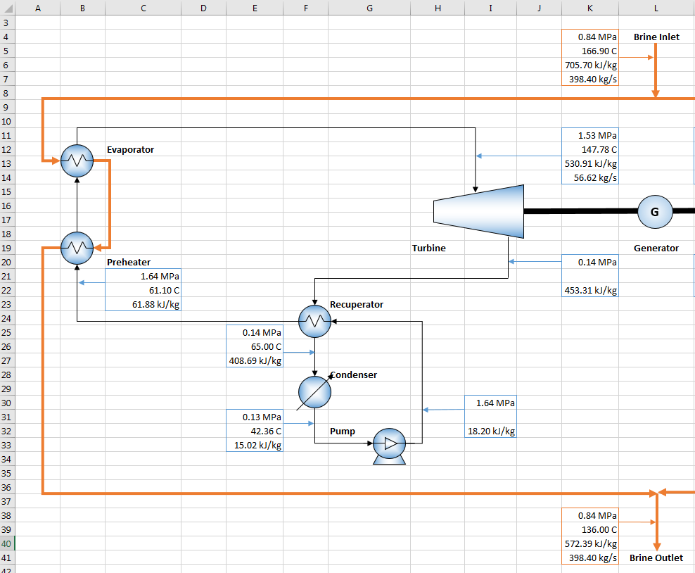
Insert the respective Style to each cell. The PFD should now look like the below figure:
Step 12 - Finding the Outlet Temperatures
There are two temperature values in the PFD sheet that we need to be calculated, i.e. the turbine outlet temperature and the pump outlet temperature.
To find the outlet temperatures, enter the following expression in cell K21 and I31, respectively:
- K21 -
=TmPH(RefrigMixtures!D3,PFD!K20,PFD!K22) - I31 -
=TmPH(RefrigMixtures!D3,PFD!I30,PFD!I32)
Insert the temperature Style to both cells.
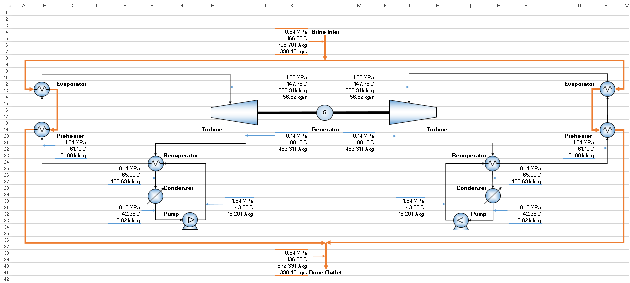
Step 13 - Copying the Thermodynamic Conditions
In order to fully complete the model, copy the thermodynamic conditions of the left-hand side to the respective right-hand side cells, remembering you could use real plant data here if available. Your final PFD of the ORC system should look like the figure below:
Conclusion
This concludes the JSteam tutorial on utilizing the ORC Unit Operations. You may like to change the temperature and pressure values at different stages of the ORC system and see how they affect the performance of the plant, as well as the isentropic efficiency of the turbine. The completed solution is available in the JSteam Examples folder.
Reference
[1] P. Moya and R. DiPippo, "Unit 5 bottoming binary plant at Miravalles geothermal field, Costa Rica: Planning design, performance and impact," Geothermics,. vol.36, no.1, pp.63-96, 2007.