Tutorial: Two Header Steam System Modelling
Introduction
This tutorial will show the basics of creating a utility model in Excel using JSteam. Please ensure you have read the Getting Started Guide before starting this tutorial.
This model assumes the standard JSteam units (°C,bar,tonne/hr,kW,mass basis).
Step 1 - Draw the PFD
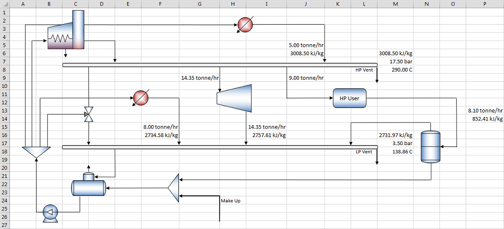
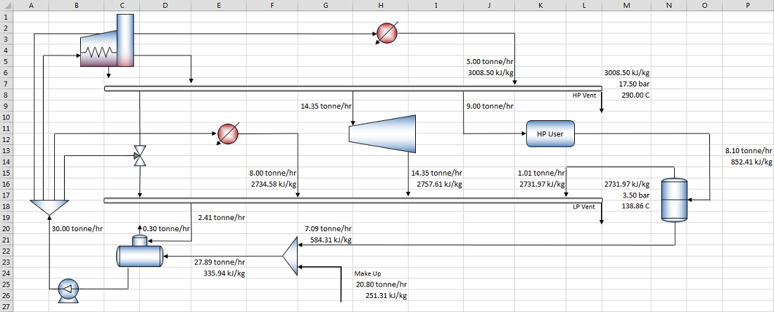
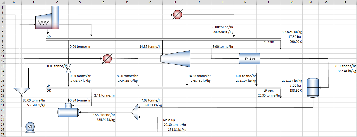
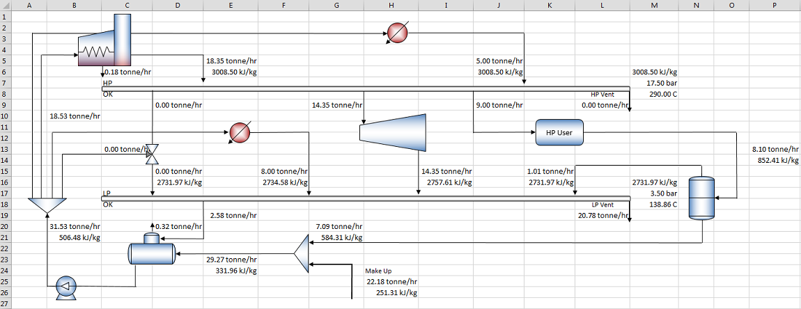
The first step building a utility model is to create the Process Flow Diagram (PFD). Begin by starting a new workbook in Excel, and drawing the PFD exactly as you see in the finished example below.
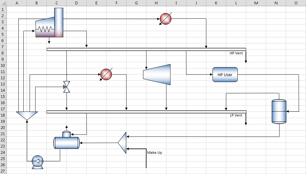
If you wish to skip the drawing step, you may open the finished PFD from the Examples directory inside the JSteam installation directory.
Step 2 - Enter Steam Header Specifications
We now begin entering the known information about our system into the PFD. The first step is to enter the steam header specifications:
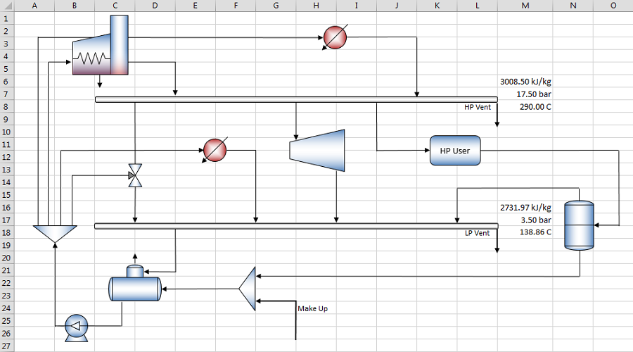
HP Header
- Pressure - Enter 17.5 in cell M7 and use the "Insert Style" function to select this as pressure.
- Enthalpy - As the header enthalpy is a calculated value we will need to first estimate it, so we will estimate it in cell M6. Type the following expression in, assuming a guess of 290°C as the header temperature
=Estimate(HPT(M7,290))
Note we have omitted the second argument of the Estimate() function at this point. Once we have a calculated value for the actual enthalpy, we will insert it into this function. Insert the Specific Enthalpy style into cell M6.
- Temperature - We will back calculate the temperature using the following function in cell M8:
=TPH(M7,M6)
Apply the Temperature style to cell M8.
LP Header
- Pressure - Enter 3.5 in cell M17 and use the "Insert Style" function to select this as pressure.
- Enthalpy - This header enthalpy is also calculated, thus we must estimate this as well. This time we will assume a guess of saturated enthalpy for the header, insert into cell M16:
=Estimate(HPX(M17,1))
Insert the Specific Enthalpy style into cell M16.
- Temperature - We will estimate the temperature using the following function in cell M18:
=Estimate(TsatP(M17))
Apply the Temperature style to cell M18.
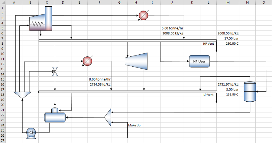
Step 3 - Enter Fixed Producer Steam Flows
Commonly excess process heat is used via a Waste Heat Boiler (WHB) in a utility system to generate steam. This is fed into the utility system based on the steam properties. As the process is not modelled, this is represented as fixed steam flows entering via heaters. You may also model these as fixed duty, but for this example fixed flow is simpler.
HP WHB
- Mass Flow - Enter 5.0 in cell J5 and paste the Flow style.
- Enthalpy - Enter the following formula in cell J6:
=HPT(M7,290)
And paste the Specific Enthalpy style. We assume a constant temperature of 290°C for this producer based on the process heat. Note how we do not enter the pressure specification again, rather reference it to cell M7. It is good modelling practice to only enter a specification once per model.
LP WHB
- Mass Flow - Enter 8.0 in cell F15 and paste the Flow style.
- Enthalpy - Enter the following formula in cell F16:
=HPT(M17,140)
And paste the Specific Enthalpy style.
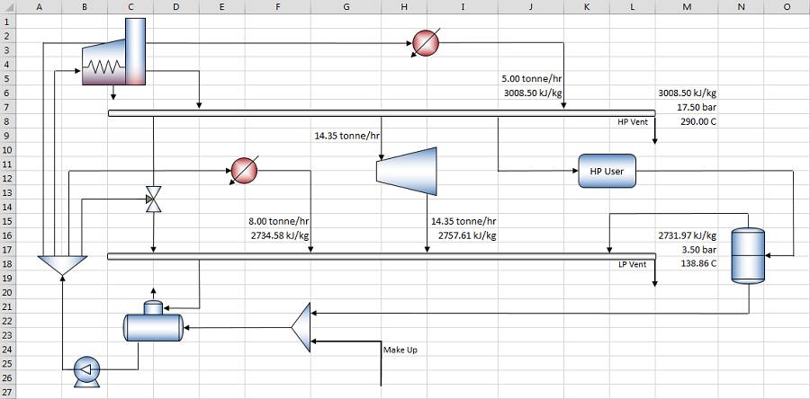
Step 4 - Enter Steam Turbine Specifications
The steam turbine is duty based, supplying 1000kW of shaftwork to the utility system at 75% isentropic efficiency. Click on cell I15 and use the Insert Function interface to paste a Turbine1Q (Steam Unit Operations -> Steam Turbines) into the current cell. Do not place a table or list arguments. The following formula will be entered:

We know all the specifications of this turbine, so fill it out as follows:

Where the inlet enthalpy is HP header enthalpy, inlet pressure is HP header pressure and outlet pressure is the LP header pressure. Enter the fixed specifications of 75% (0.75) efficiency and 1000kW, and press CTRL+SHIFT+ENTER to evaluate the array function. Copy the resulting mass flow to cell G9 (as a cell reference, e.g. =I15), as we will use this for the header balance later on.
Step 5 - Enter Steam User Steam Flows
Most steam headers will supply steam to various process users around the facility and these are modelled as fixed steam flows via Users. Some of these users will return all the steam via condensate, and others will return a proportion. The returning condensate temperature and pressure will vary according to the process user. In this tutorial the HP User requires 9 ton/h of HP steam, and returns 90% of this as condensate. The user has a pressure drop of 1.5 bar, and returns the condensate at 200°C.
- Inlet Mass Flow - Enter 9.0 in cell J9 and insert the Flow style.
- Outlet Mass Flow - Enter the following formula in cell P13:
=J9*0.9
And insert the Flow style.
- Outlet Enthalpy - Enter the following formula in cell P14:
=HPT(M7-1.5,200)
And insert the Specific Enthalpy style.
Step 6 - Enter Flash Drum Specifications
The flash drum collects the condensate returning from the HP user and drops the pressure to the pressure of the LP header. This pressure drop recovers some of the steam which is returned to the LP header. The remainder is returned to the deaerator.
We will place the Flash Drum function on Sheet 2, which you should rename to "Plant_Equipment". Use the Insert Function interface to paste the Flash Drum unit operation with table and arguments listed into cell A2. Connect the operating pressure to PFD!M17 (LP Pressure), inlet enthalpy to PFD!P14 (HP User return enthalpy) and inlet mass flow to PFD!P13 (HP user return mass flow):
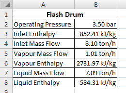
With the above specifications entered, we can connect the results back to the PFD. By placing this function on another sheet, we can keep our PFD free from clutter and avoid mistakes later on. Connect the following cells:
- Vapour Mass Flow -> PFD Cell K15
- Vapour Enthalpy -> PFD Cell K16
- Liquid Mass Flow -> PFD Cell G20
- Liquid Enthalpy -> PFD Cell G21
Insert the respective styles as required.
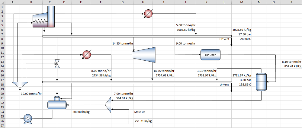
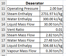
Step 7 - Solve Deaerator using Estimates
In order to solve the deaerator we will need to make two estimates, one of the incoming enthalpy to the deaerator, and one of the required mass flow of water leaving the deaerator.
- Make Up Water - Enter the make up water specifications in cell H26 as 2 bar, 60°C:
=HPT(2,60)
And paste the Specific Enthalpy style.
- Condensate Enthalpy - Next enter an estimate of the enthalpy to the deaerator as 300kJ/kg (based on the two streams being mixed) in cell E24:
=Estimate(300)
And paste the Specific Enthalpy style.
- Outlet Mass Flow - Enter an estimate of the outlet mass flow as 30 ton/h in cell B20:
=Estimate(30)
And paste the Flow style.
With the above values, we can now solve the deaerator. On the Plant_Equipment sheet use the Insert Function interface to paste the deaerator with table and arguments listed into cell A11. Enter the following specifications:
- Operating Pressure - 2 bar
- Steam Enthalpy - Connect to cell PFD!M16 (LP Header Enthalpy)
- Water Enthalpy - Connect to cell PFD!E24 (Estimate of condensate enthalpy)
- Liquid Mass Flow - Connect to cell PFD!B20 (Estimate of BFW mass flow)
- Vent Ratio - 0.01
Step 8 - Solve Condensate Enthalpy
Now we have a mass flow of condensate required (Water Mass Flow) we can calculate the actual condensate enthalpy. This is an iterative calculation, so ensure iterative calculation is enabled in your workbook.
Begin by copying the mass flow results from the deaerator to the PFD:
- Steam Mass Flow -> PFD Cell E19
- Water Mass Flow -> PFD Cell E23
- Vapour Mass Flow -> PFD Cell D20
Now we can complete the mass balance of the mixer. Enter the following formula in cell H25 to calculate the make up water mass flow:
=E23-G20
Finally we can calculate the condensate enthalpy using a mass weighted enthalpy mix. In cell E24 enter the first argument of our estimate as follows:
=Estimate((G20*G21+H25*H26)/(G20+H25),300)
As shown above, the sheet will now iterate to a steady state where the actual enthalpy is 335.94 kJ/kg. You may need to press F9 (recalculate) a couple of times to allow the solver to converge.
Step 9 - Enter Pump Specifications
The BFW pump can now be solved, which will result in the true BFW enthalpy. This will allow us to calculate the letdown flows in the following steps.
On the Plant_Equipment Sheet using the Insert Function interface, insert a Pump function into cell D11 with table and arguments listed. Enter the following specifications:
- Inlet Enthalpy - Connect to Plant_Equipment cell B18 (deaerator outlet enthalpy)
- Inlet Pressure - Connect to Plant_Equipment cell B11 (deaerator pressure)
- Inlet Mass Flow - Connect to Plant Equipment cell B14 (deaerator liquid mass flow)
- Outlet Pressure - Connect to PFD!M7 (HP header pressure)
- Efficiency - 95%
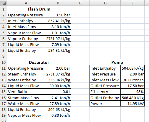
Finally connect the outlet enthalpy of the pump to PFD cell B21.
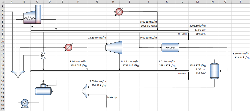
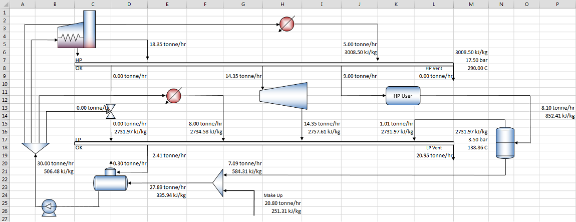
Step 10 - Complete LP Header Mass Balance
The LP header mass balance is solved by calculating the deficit of steam required (supplied by the desuperheater) and venting of steam required.
The deficit is entered in cell D15:
=MAX(E19-F15-I15-K15,0)
And the vent entered in cell L19:
=MAX(F15+I15+K15-E19,0)
Good practice is to check the header is balanced by completing a sum of all in and out flows. Enter the following formula in cell C18:
=IF(ABS(D15+F15+I15+K15-L19-E19)<0.000001,"OK","ERROR")
Which checks to see if the total balance is less than 1e-6, in which case it will return "OK".
Alternatively you may also like to calculate the total fixed in and out for the header, and use these for the deficit and vent calculations.
Step 11 - Enter Desuperheater Specifications
Although currently the desuperheater is supplying no steam, in some operating conditions it may thus we must still model it.
On the Plant_Equipment sheet using the Insert Function interface paste a DesuperheaterMout into cell A22 with table and arguments listed. Enter the following specifications:
- Steam Enthalpy - Connect to PFD!M6 (HP header enthalpy)
- Water Enthalpy - Connect to PFD!B21 (BFW enthalpy)
- Outlet Pressure - Connect to PFD!M17 (LP header pressure)
- Outlet Temperature - Connect to PFD!M18 (LP header temperature)
- Outlet Mass Flow - Connect to PFD!D15 (LP header deficit)
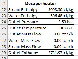
Copy the results back to the PFD:
- Water Mass Flow -> Connect to PFD Cell C13
- Steam Mass Flow -> Connect to PFD Cell D9
- Outlet Enthalpy -> Connect to PFD Cell D16
Step 12 - Complete HP Header Mass Balance
We can now complete the mass balance of the HP header.
The deficit is entered in cell E5:
=MAX(D9+G9+J9-J5,0)
And the vent entered in cell L9:
=MAX(J5-D9-G9-J9,0)
And the balance check in cell C8:
=IF(ABS(E5+J5-G9-J9-L9-D9)<0.000001,"OK","ERROR")
Step 13 - Enter Boiler Specifications
Rename Sheet 3 to "Producers" and using the Insert Function interface paste a Boiler into cell A2 with table and arguments listed. Enter the following specifications:
- BFW Enthalpy - Connect to PFD!B21 (BFW enthalpy)
- Steam Mass Flow - Connect to PFD!E5 (HP header deficit)
- Steam Temperature - 290°C
- Steam Pressure - Connect to PFD!M7 (HP header pressure)
- Blowdown Ratio - 0.01
- Firing Efficiency - 93%
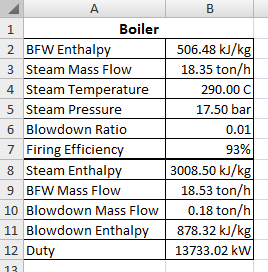
Copy the results back to the PFD:
- Steam Enthalpy -> Connect to PFD cell E6
- BFW Mass Flow -> Connect to PFD cell B10
- Blowdown Mass Flow -> Connect to PFD cell C6

Step 14 - Complete System Mass Balance
We can now complete the mass balance of the system as we know the required BFW mass flows of each piece of equipment.
Append the following to our initial estimate of BFW mass flow in cell B20:
=Estimate(B10+C13+F15+J5,30)
Once again this is an iterative solution, and the sheet should converge to:
Step 15 - Complete LP Header Energy Balance
We can now complete the energy balance of the LP header and correctly calculate the header enthalpy. Using a mass weighted enthalpy mix as done around the condensate mixer, we can mix the streams entering the LP header and calculate the resulting enthalpy.
Append the following to our initial estimate of header enthalpy in cell M16:
=Estimate((D15*D16+F15*F16+I15*I16+K15*K16)/(D15+F15+I15+K15),HPX(M17,1))
And append the following to our initial estimate of header temperature in cell M18:
=Estimate(TPH(M17,M16),TsatP(M17))
Which will calculate the true temperature based on the enthalpy calculated.

Step 16 - Complete HP Header Energy Balance
Following the same principle for the LP header, we can complete the HP header energy balance.
Append the following to our initial estimate of header enthalpy in cell M6:
=Estimate((E5*E6+J5*J6)/(E5+J5),HPT(M7,290))
Which based on the equal temperature streams entering the header will result in the same enthalpy as our estimate.
Conclusion
This concludes the first system tutorial on JSteam. Feel free to change the numbers in the tutorial to see how the system solves. You may like to calculate the cost of this system (Boiler MW - Turbine kW + Make Up ton/h) and see if you can optimize the system's operation. The completed solution is available in the examples folder on your PC.

Copyright © Control Engineering