Steam Unit Operations
In addition to suppling thermodynamic and transport routines, JSteam also provides a suite of models (known as unit operations) for modelling subsystems and equipment within heat and power plants. This page covers the water and steam unit operations, which relies only on the Steam Thermodynamics functionality included in JSteam.
To view available unit operations, use JSteamMEX('help') under the WATER & STEAM UNIT OPERATIONS heading. They are grouped as follows:
- Boilers
- A simple boiler model which superheats water into steam.
- Compressors
- Single and multi-stage compressors, with duty and mass flow variants.
- Coolers & Heaters
- Simple duty and mass flow specified heaters and coolers.
- Plant Equipment
- Other models such as valves, pumps, deaerators, and flash drums.
- Expanders/Turbines
- Single and multi-stage expanders/turbines, with duty and mass flow variants.
Example: Steam Boiler
As per the help page in the JSteam Excel Help Manual Examples/JSteam Excel Help.chm:
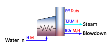
Calculates the required duty to heat the Boiler Feed Water (BFW) to the required steam temperature and pressure, with specified continuous blowdown ratio and firing efficiency.
From the JSteamMEX Help print out:
and following Examples/JSteam_UnitOps.m:
BFWT = 25; % Inlet Boiler Feed Water Temperature [C]
BFWP = 5; % Inlet Boiler Feed Water Pressure [bar]
BFWH = JSteamMEX('HPT',BFWP,BFWT); % Inlet Boiler Feed Water Enthalpy [kJ/kg]
StmM = 5; % Outlet Steam Mass Flow Rate [tonne/h]
StmT = 410; % Outlet Steam Temperature [C]
StmP = 42; % Outlet Steam Pressure [bar]
BDr = 0.01; % Blowdown Ratio [fraction]
Eff = 0.9; % Firing Efficiency [fraction]
[status,StmH,BFWM,BDM,BDH,Duty] = JSteamMEX('UnitOp_Boiler',BFWH,StmM,StmT,StmP,BDr,Eff)
the routine will calculate the Steam Enthalpy (StmH), Boiler Feed Water Mass Flow Rate and Enthalpy (BFWM, BFWH) and Duty (Duty). It will also return a status code, where 1 is success, and 0 and below is a failure.
Example: Multi-Stage Turbine
As per the help page in the JSteam Excel Help Manual Examples/JSteam Excel Help.chm:
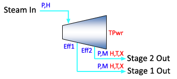
Dual stage flow based steam turbine.
From the JSteamMEX Help print out:
and following Examples/JSteam_UnitOps.m:
inT = 410; % Inlet Temperature [C]
inP = 42; % Inlet Pressure [bar]
inH = JSteamMEX('HPT',inP,inT); % Inlet Enthalpy [kJ/kg]
outP1 = 15; % First Stage Outlet Pressure [bar]
Eff1 = 0.4; % First Stage Isentropic Efficiency [fraction]
outM1 = 10; % First Stage Outlet Mass Flow [tonne/hr]
outP2 = 3; % Second Stage Outlet Pressure [bar]
Eff2 = 0.5; % Second Stage Isentropic Efficiency [fraction]
outM2 = 4; % Second Stage Outlet Mass Flow [tonne/hr]
[status,TPwr,outH1,outH2] = JSteamMEX('UnitOp_Turbine2M',inH,inP,outP1,Eff1,outM1,outP2,Eff2,outM2)
the routine will calculate the Total Output Power (TPwr), and first and second stage outlet enthalpy (outH1, outH2) as a result of expanding the incoming steam to the specified lower pressures, at the specified mass flow rates. It will also return a status code, where 1 is success, and 0 and below is a failure.
Note that JSteam provides expanders with single (1M), dual (2M) and triple (3M) stage functionality, as well as providing "duty based" (1Q/2Q/3Q) functionality, where you specify the total output power, and it will compute the mass flow rate of a stage to match it.
Example: Modelling a Heat Exchanger
Heat and power systems commonly use heat exchangers in order to capture waste heat and reuse it to increase overall system efficiency. JSteam does not provide "traditional" heat exchanger models (such as those with LMDT or E-NTU methods), but you are able to approximate exchangers using a pairing of a cooler and heater. This technique works just as well provided you are not trying to solve exchangers that are specified using UA or LMDT, and you take careful (manual) checks to ensure the delta-T is physical.
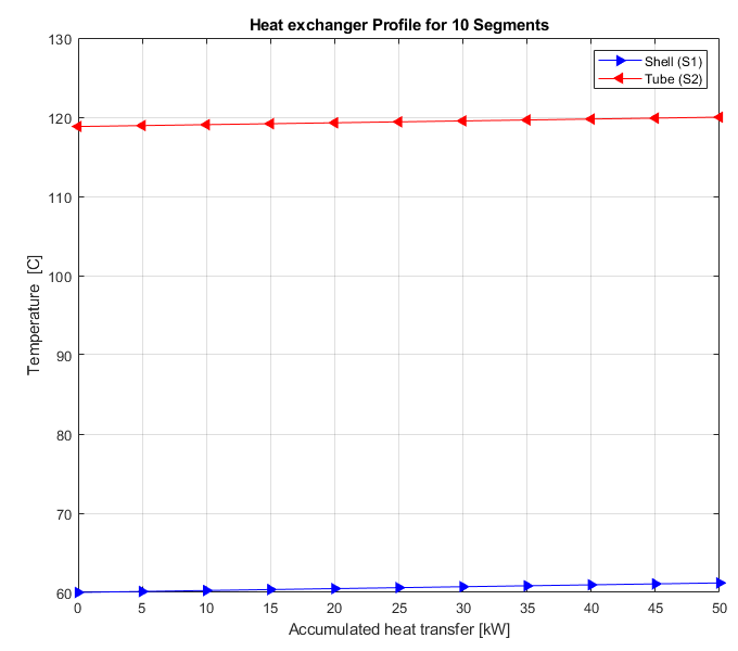
Counter Flow Shell & Tube, No Phase Change, Liquid/Liquid
In the below example we are provided with the input conditions of heat exchanger (input pressures, temperatures and mass flow rates), and have made some assumptions on the outlet conditions (no pressure drop, no mass loss) to simplify the example (note it is easy to add real losses too!). We also have the total duty of the heat exchanger, which makes this a trivial example to solve. Based on this information, we choose heaters and coolers based on the information we can input, and what we can calculate.
shell.inP = 10; % Shell, Inlet Pressure [bar]
shell.inT = 60; % Shell, Inlet Temperature [C]
shell.inM = 36; % Shell, Inlet Mass Flow Rate [tonne/hr]
tube.inP = 10; % Tube, Inlet Pressure [bar]
tube.inT = 120; % Tube, Inlet Temperature [C]
tube.inM = 36; % Tube, Inlet Mass Flow Rate [tonne/hr]
duty = 50; % Heat Exchanger Duty [kW]
% Solve Heater (shell) - Know M+Q, Solve H+T
shell.inH = JSteamMEX('HPT',shell.inP,shell.inT); % Inlet Enthalpy [kj/kg]
shell.outP = shell.inP; % Assume no pressure drop, [bar]
shell.outM = shell.inM; % Assume no mass loss [tonne/hr]
[status,shell.outH,shell.outT] = JSteamMEX('UnitOp_HeaterMQ',shell.inH,shell.outP,shell.outM,duty);
% Solve Cooler (tube) - Know M+Q, Solve H+T
tube.inH = JSteamMEX('HPT',tube.inP,tube.inT); % Inlet Enthalpy [kj/kg]
tube.outP = tube.inP; % Assume no pressure drop, [bar]
tube.outM = tube.inM; % Assume no mass loss [tonne/hr]
[status,tube.outH,tube.outT] = JSteamMEX('UnitOp_CoolerMQ',tube.inH,tube.outP,tube.outM,duty);
The solution for the above exchanger has the shell outlet temperature increasing to 61.2C, while the tube outlet temperature drops to 118.83C. There is still a substantial delta-T between the inputs and outputs, thus this solution is valid. The plot below confirms this as well.
Counter Flow Shell & Tube, Phase Change, Liquid/Steam
In the below example there is boiling occurring within the shell side of the heat exchanger together with no duty specification of the overall exchanger. This would be more common in practice where you have input and output measurements, but the duty is not available. In this case, based on the availability of measurements, we solve the tube first to obtain the duty, which is then used by the shell side heater.
shell.inP = 1; % Shell, Inlet Pressure [bar]
shell.inT = 90; % Shell, Inlet Temperature [C]
shell.inM = 0.9; % Shell, Inlet Mass Flow Rate [tonne/hr]
tube.inP = 1; % Tube, Inlet Pressure [bar]
tube.inT = 500; % Tube, Inlet Temperature [C]
tube.inM = 3.6; % Tube, Inlet Mass Flow Rate [tonne/hr]
tube.outT = 150; % Tube, Outlet Temperature [C]
% Solve Cooler (tube) - Know T+M, Solve H+Q
tube.inH = JSteamMEX('HPT',tube.inP,tube.inT); % Inlet Enthalpy [kj/kg]
tube.outP = tube.inP; % Assume no pressure drop, [bar]
tube.outM = tube.inM; % Assume no mass loss [tonne/hr]
[status,tube.outH,duty] = JSteamMEX('UnitOp_CoolerTM',tube.inH,tube.outP,tube.outT,tube.outM);
% Solve Heater (shell) - Know M+Q, Sovel H+T
shell.inH = JSteamMEX('HPT',shell.inP,shell.inT); % Inlet Enthalpy [kj/kg]
shell.outP = shell.inP; % Assume no pressure drop, [bar]
shell.outM = shell.inM; % Assume no mass loss [tonne/hr]
[status,shell.outH,shell.outT] = JSteamMEX('UnitOp_HeaterMQ',shell.inH,shell.outP,shell.outM,duty);
shell.outX = JSteamMEX('XPH',shell.outP,shell.outH); % Check Phase
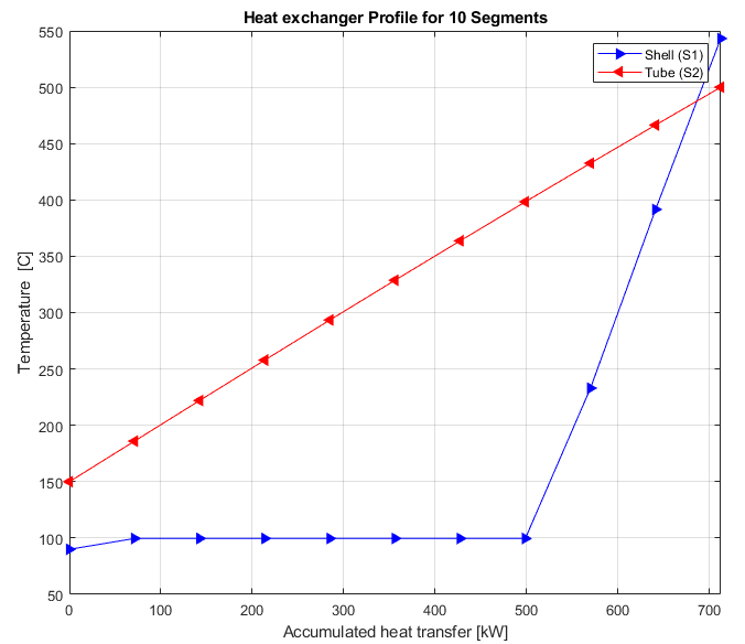
The solution for the above exchanger has the shell outlet temperature increasing to 374.3C, and the overall duty estimated as 712kW. At this operating point the exchanger has vaporized and superheated the incoming liquid, resulting in superheated steam exiting the shell.
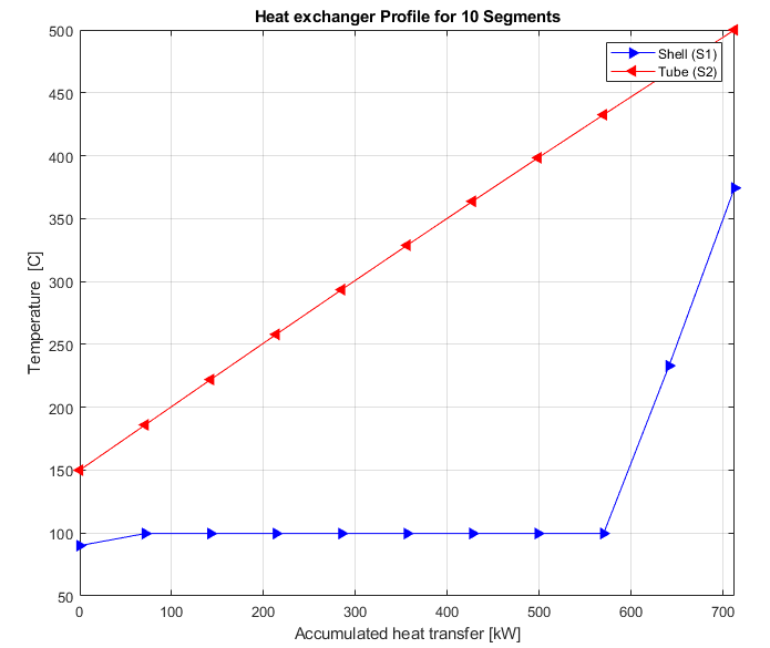
As per the above plot, the delta-T between Shell Outlet and Tube Inlet is now much closer, and must be monitored during modelling. If, for example, the shell side mass flow rate was to drop to 0.8 tonne/hr, the above modelling technique would report the shell outlet temperature as 543.18C, which is obviously impossible as the inlet temperature on the tube side is only 500C! Therefore sanity checks must be added by the user. This is visualized below showing the unphysical temperature cross:
If you are interested how I generated the above plots - they are from some old models of HX that was going to be added to JSteam - but I ran out of time!